The electrolytic cell is a crucial component in the aluminum electrolysis process, and the two main factors affecting its lifespan are the carbon cathode and the refractory lining. This section explores the application of silicon carbide refractory bricks in aluminum electrolytic cells and the current challenges they face.
Aluminum electrolytic cell linings can be categorized into bottom linings and side linings. The bottom lining functionally supports the cathode structure and provides insulation. The side linings primarily protect the steel outer shell from corrosion by the molten electrolyte.
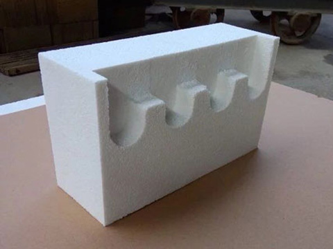
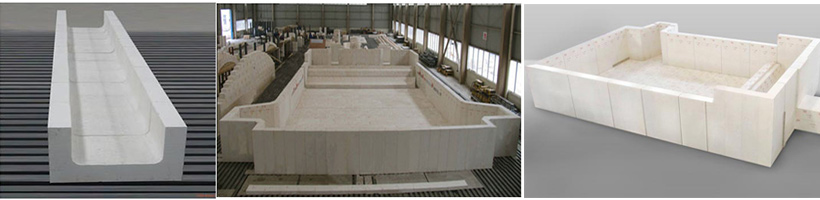
Aluminum Electrolytic Cell
The side lining of an aluminum electrolytic cell is a crucial structural component. Modern concepts dictate that the sidewall material should possess the following important properties at high temperatures: high resistivity, good thermal conductivity, non-reactive to molten cryolite, low porosity, impermeability to electrolyte and aluminum, and resistance to air oxidation.
Since silicon carbide’s valence bond structure determines its superior properties, such as high strength, high hardness, high temperature resistance, oxidation resistance, high thermal conductivity, low thermal expansion coefficient, excellent thermal shock resistance, good chemical stability, and non-wetting by non-ferrous metals, and also exhibits good resistance to high-temperature chemical corrosion, it is particularly suitable as a refractory lining material for aluminum electrolytic cells.
With advancements in materials technology and the increasing capacity of electrolytic cells, the structure of the side lining material has evolved from the early double carbon block plus insulating brick structure to single-layer carbon blocks without insulating bricks, and ultimately to today’s single silicon carbide combined with silicon nitride materials.
Problems and Current Research Status
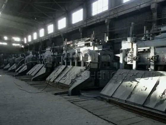
Silicon carbide refractory bricks are a new type of furnace-building material recently promoted and used in the non-ferrous metals industry, initially applied to a 320kA large prebaked aluminum electrolytic cell in an aluminum plant. In recent years, user experience has shown that regardless of whether pure silicon carbide refractory brick side blocks or composite side blocks are used, varying degrees of cracking and detachment have been commonly observed during production, with the silicon carbide layer in composite side blocks also exhibiting upward lifting.
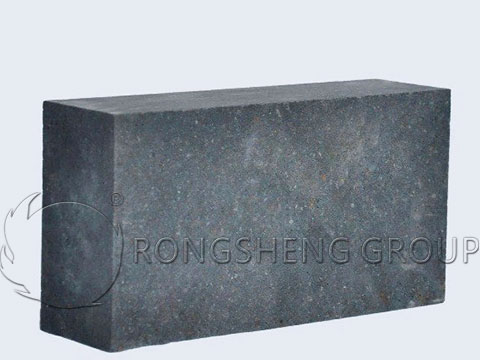
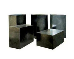
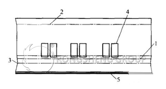
Silicon Carbide Bricks
Temperature difference (with the upper edge of the artificial extension leg as the boundary) is the main cause of silicon carbide brick cracking. Although silicon carbide bricks have good thermal conductivity and a low coefficient of thermal expansion, because the products are fired at temperatures above 1450℃, forming a hexagonal ceramic structure, their resistance to thermal shock and temperature differences is poor. Under environments where repeated temperature differences are formed between the upper and lower parts of the silicon carbide refractory brick, it is extremely prone to cracking.
When the silicon carbide composite layer fractures, electrolyte seeps into the crack. When the electrolytic cell returns to normal temperature from the initial effect temperature, the electrolyte in the crack solidifies and shrinks, and new electrolyte enters and solidifies again. During the next effect, the solid electrolyte in the crack expands due to heat, pushing up the upper fractured block. When the cell temperature returns to normal, the electrolyte solidifies and shrinks again, forming a gap. Then, new electrolyte enters and solidifies again. During the next effect, expansion pushes the fractured block up again, and this process repeats, gradually raising the upper part of the fracture.
During aluminum electrolysis, the temperature approaches 1000℃. At this temperature, the erosion of the electrolytic cell lining mainly consists of three parts: the molten aluminum near the bottom, the molten electrolyte in the middle, and various corrosive gases (such as HF, AlN, and AlF4) in the upper part. Typically, in the electrolyte-alumina molten liquid, cation penetration is mainly Na+, and anion penetration is mainly F-.
Porosity, matrix phase, wettability, and other factors can all affect the erosion resistance of refractory materials. Materials with high porosity and large pore size generally have poor corrosion resistance because cryolite or molten aluminum can directly penetrate into the material’s interior. The limiting pore sizes of molten metal in refractory materials are 30 μm for molten steel, 5 μm for molten iron, and 0.5 μm for molten aluminum; therefore, molten aluminum has a very strong penetrating ability. A thin matrix phase results in good corrosion resistance, but its strength is directly affected; a thick matrix phase results in poor corrosion resistance. A large wetting angle between the material and molten aluminum leads to superior corrosion resistance.
The resistance of SiC materials with various bonding phases to electrolyte corrosion was studied. The results showed that, except for self-bonded SiC, Si3N4-bonded SiC materials exhibited the best electrolyte resistance. Although the Si3N4 bonding phase was wetted by the melt, the penetration was shallow and no decomposition occurred.
The results indicate that damage to Si3N4-bonded SiC products in the air interface is mainly due to the oxidation of Si3N4 and SiC. At the cryolite electrolyte-air interface, the vicious cycle of oxidation-erosion-penetration formed by chemical reactions results in the most severe corrosion. The dissolution of electrolytes in molten aluminum and the porosity of the sample structure itself are likely the main reasons for the corrosion of Si3N4-bonded SiC products in molten aluminum.
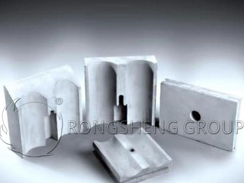
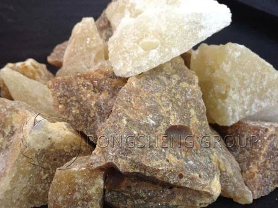
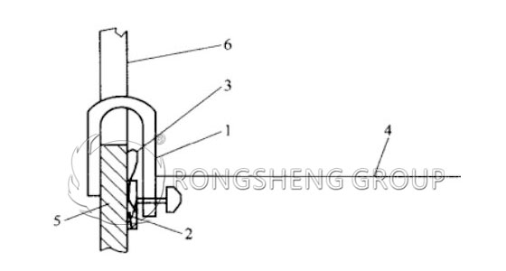
Silicon Nitride-Bound Silicon Carbide Bricks
The erosion behavior of silicon nitride-bound silicon carbide refractories with different silicon nitride contents in cryolite molten salt was studied. The results showed that corrosion mainly occurred before 25 hours. After 25 hours, the weight gain of the Si3N4/SiC material remained essentially unchanged, while the Si3N4/SiC material with a low Si3N4 content (13%) exhibited good resistance to cryolite melt corrosion.
The study found that during aluminum electrolysis, porosity and β-Si3N4 content significantly affected the erosion resistance of Si3N4-bound SiC refractories. Higher porosity or higher β-Si3N4 content resulted in more severe erosion. A SiC aggregate content between 80% and 85% showed good erosion resistance.