Refractory Materials Used in Thermal Power Generation Projects

Refractory materials used in thermal power generation projects are diverse. Based on application scenarios and performance requirements, they can be mainly classified into the following categories:

Shaped Refractory Products

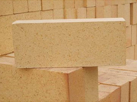
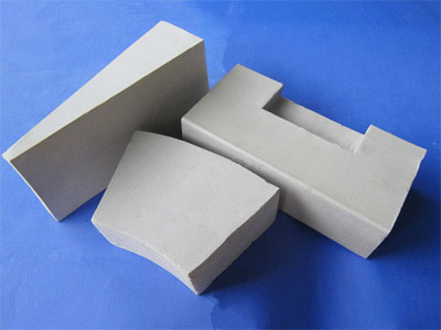
  • Clay Refractory Bricks: Made primarily of refractory clay, containing 30%-46% alumina, with a refractoriness of 1580-17700℃, good thermal shock resistance, suitable for boiler walls, furnace roofs, etc., and resistant to acidic slag corrosion.
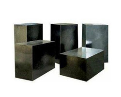
  • High-Alumina Refractory Bricks: Containing 48%-90% alumina, with a refractoriness ≥1700℃, high compressive strength, and high load softening temperature, commonly used in high-temperature areas of boilers, such as the furnace chamber and furnace bottom, and also exhibiting some resistance to alkaline slag corrosion.
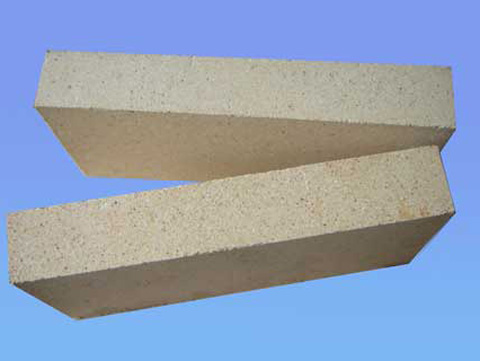
  • Silica Bricks: Containing over 94% silica, with strong resistance to acidic slag corrosion and a high load softening temperature, but poor thermal shock resistance. Primarily used in acidic environments such as coke ovens and glass melting furnaces, and less commonly used in boiler bodies in thermal power generation, mostly in auxiliary equipment.
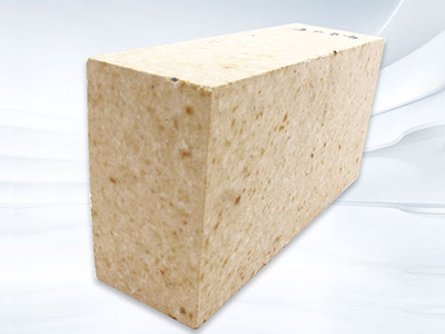
  • Magnesia bricks: with magnesium oxide as the main component, containing more than 80%-85% magnesium oxide, the refractoriness is higher than that of clay bricks and silica bricks. They have good resistance to alkaline slag and iron slag and are often used in alkaline environments such as open-hearth furnaces and oxygen-blown converters. They are also used in specific high-temperature equipment in thermal power generation.

Unshaped Refractory Materials

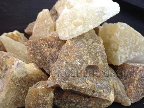
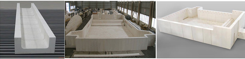
  • Refractory Castables: Composed of aggregates, fine powder, and binders, delivered in a dry state. Mixed with water before casting. Suitable for complex-shaped parts such as boiler furnaces, bottoms, and tops. Common types include clay-based, high-alumina, phosphate-bonded, and water glass-bonded. Features high compressive strength, thermal shock resistance, and abrasion resistance.
  • Refractory Plastics: Composed of aggregates, fine powder, binders, and liquid. Possesses good plasticity. Applied by ramming. Hardens upon heating after application. Suitable for boiler furnace walls and tops. Adaptable to complex shapes and temperature changes, offering good thermal shock resistance and abrasion resistance.
  • Refractory Rammed Mixtures: Non-adhesive before use. Applied by ramming. Suitable for boiler furnace bottoms and walls. Forms a dense refractory layer with high compressive strength and abrasion resistance.
  • Refractory mortar: Composed of refractory powder, binder, and additives, it is mixed with water to form a slurry. It is used as a joint material for shaped refractory products, ensuring the sealing and refractoriness of the joints.

Insulating Refractory Materials

  • Insulating Refractory Bricks: Such as clay insulating bricks, high-alumina insulating bricks, diatomaceous earth insulating bricks, etc., with a true porosity ≥45%, low bulk density, and low thermal conductivity, used as insulation layers in boiler furnace walls, roofs, and bottoms to reduce heat loss.
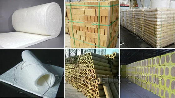
  • Ceramic Fiber Products: Including ceramic fiber blankets, ceramic fiber boards, ceramic fiber modules, etc., these products are heat-resistant (up to 1260℃ and above), have extremely low thermal conductivity, and good thermal shock resistance. They are used for insulation and heat preservation in boiler furnaces, roofs, and walls, effectively reducing heat loss.
  • Rock wool products: Made from natural rock through high-temperature melting, they possess low thermal conductivity, high refractory limit, and good mechanical strength. They are used for heat insulation and thermal insulation of boiler furnace walls, roofs, and bottoms, and are particularly suitable for environments requiring fireproofing and heat insulation.

The selection of the above refractory materials must be based on a comprehensive consideration of factors such as the specific application scenario of the thermal power plant project, temperature, slag properties, and mechanical load to ensure the safe and efficient operation of boilers and other equipment.

How to Implement High-Temperature Thermal Insulation Solutions for Power Plants?

A thermal power plant, or CDP, is a factory that uses the chemical energy of coal, oil, natural gas, or other fuels to produce electricity. A thermal power plant’s generator unit consists of three main components: a boiler, a steam turbine, and a generator, along with numerous auxiliary equipment and piping.

Thermal Insulation Solutions for Power Plants

Common Thermal Insulation Materials for Power Plants

External thermal insulation materials for power plants: Aluminum silicate fiber blankets, rock wool, glass wool, silicate boards, felt, pipe shells, boards, cloth, calcium silicate boards, pipe shells, aerogel composite insulation felt.

Other refractory materials for power plant insulation: Acid-resistant castables, wear-resistant castables, various light and heavy castables, refractory bricks, insulating bricks.

Zoned Thermal Insulation Solutions for Power Plants

The key to power plant insulation is first to divide the area into three main insulation zones based on application zoning. After on-site investigation, each zone is divided into three main insulation sections, and then insulation solutions are designed for each section.

High-Temperature Insulation Solution for Power Plant Boilers

Power plant boiler insulation includes the boiler body and some auxiliary equipment. Fuel burns in the boiler furnace, releasing heat energy. This heat is transferred through the metal walls, converting the water in the boiler into superheated steam with a certain pressure and temperature. The steam is then sent to the turbine, which drives the generator to produce electricity. The temperature of the superheated steam inside the boiler is 540℃.

Power Plant Boiler Body Insulation Solution

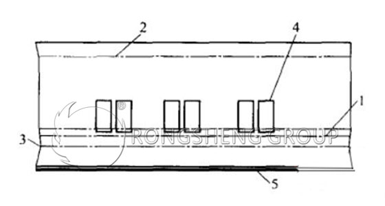
The main insulation layer of the power plant boiler body consists of: high-temperature anti-corrosion coating (anti-corrosion layer) + 100mm rock wool felt or ceramic fiber blanket (insulation layer) + galvanized flexible wire mesh (binding layer) + plastering material (surface layer) + ceramic fiber blanket (protective layer b) + fiberglass cloth (protective layer a) + aluminum powder heat-resistant paint (surface layer).

Insulation Material Selection for Other Insulation Components of the Boiler Insulation System

  • Boiler Water-Cooled Wall Insulation: Alumina Bricks + Rock Wool Board
  • Furnace Top Cover Insulation: Ceramic Fiber + Rock Wool Board
  • Furnace Top Cover Top Insulation: Refractory Castable
  • Furnace Inner Header Insulation: Ceramic Fiber Board, Ceramic Fiber Blanket
  • Steam Drum Insulation Material: Ceramic Fiber Blanket + Rock Wool Board
  • Downcomer Insulation: Ceramic Fiber Board, Ceramic Fiber Blanket + Rock Wool Board
  • Furnace Wall Insulation at Flue Corner: Ceramic Fiber Modules, Ceramic Fiber Blanket + Rock Wool Board
  • Air Preheater Insulation Material: Ceramic Fiber Board, Ceramic Fiber Modules, Ceramic Fiber Blanket + Rock Wool
  • Boiler Hot Air Duct Insulation: Ceramic Fiber Blanket Insulation + Rock Wool
  • Boiler Body Flue Insulation: Ceramic Fiber Module Insulation, Ceramic Fiber Blanket + Rock Wool
  • Electrostatic Precipitator Insulation: Rock Wool Board

High-Temperature Insulation Solutions for Steam Turbines

A steam turbine is a rotary power machine whose primary function is to convert the thermal energy of steam into mechanical energy.

The correctness and rationality of the structural design of the steam turbine insulation device, and the appropriateness of the selection of insulation materials, are crucial to the thermal economy and long-term operational safety of the steam turbine unit.

In the past, some power plant and shipyard steam turbines suffered from unreasonable insulation device structural design and inappropriate insulation material selection. This resulted in large temperature differences between the upper and lower cylinders, as well as large temperature differences between the inner and outer walls of the cylinders and flanges, leading to severe unit deformation and affecting the safe operation of the unit.

In my country, some power plants, shipyards, and industrial steam turbines have gradually replaced their insulation with new, detachable insulation structures. The lower cylinder uses a fixed insulation structure.

Upper Cylinder

Detachable insulation sleeve + outer protective layer (stainless steel plate or fiberglass), manufactured in sections and modules.

The inner layer of the removable insulation jacket for the steam turbine is either high-temperature resistant ceramic fiber cloth (resistant to 1260℃, long-term use at 1000℃) or high-silica cloth (resistant to 1000℃, long-term use at 950℃).

The inner core layer of the removable insulation jacket is a 240mm ceramic fiber blanket.

The outer layer of the removable insulation jacket for the steam turbine is silicone cloth.

Lower Cylinder

Fixed insulation structure (similar to boiler body insulation), insulation thickness is 1.1 times that of the upper cylinder.

Cylinder center split flange

Removable insulation jacket + outer protective layer (stainless steel plate or fiberglass), manufactured in sections and blocks.

Different insulation materials can be replaced according to actual application conditions, thereby changing the thickness and size to meet the insulation installation requirements of tight spaces between equipment.

Steam Pipeline Insulation Solution for Power Plants

A detachable insulation structure is adopted, with an insulation layer thickness of 180mm (90mm x 2 layers of ceramic fiber blanket).

Inner layer of the steam pipeline insulation jacket: Medium-alkali fiberglass cloth (resistant to 600℃, long-term use at 450℃);

Inner core layer of the steam pipeline insulation jacket: 180mm ceramic fiber blanket;

Outer layer of the steam pipeline insulation jacket: Silicone cloth/fiberglass reflective cloth.

The thickness of the inner core of the detachable insulation jacket is adjusted according to the three different pipe temperatures.

The Thermal Ceramic Detachable and Reusable Insulation Jacket (Pack) is a new generation of flexible thermal insulation product. Its advantages include detachability and reusability, meeting the insulation requirements of high-temperature working bodies that require regular maintenance or inspection.

Advantages of using detachable insulation sleeves on steam turbines:

  • Low thermal conductivity, excellent insulation effect;
  • Saves installation and maintenance time, significantly shortening the construction cycle and indirectly generating profits;
  • Can be disassembled and reused multiple times;
  • Flexible insulation, resistant to stepping and impact;
  • Outer layer is oil and water resistant, and resistant to acid and alkali corrosion;
  • Multiple installation options, convenient installation with no exposed areas;
  • Beautiful and clean product appearance, washable surface;
  • Long service life.

What are the Effects of the Main Raw Materials in Aluminum-Magnesium-Carbon Bricks on Their Performance?

Carbon-based refractories are a new type of refractory material developed in the late 1970s. Utilizing the high refractoriness and non-wetting properties of graphite, they significantly improve the high-temperature performance and erosion resistance of refractory materials. They possess excellent thermal shock stability, slag erosion resistance, spalling resistance, and high-temperature creep resistance. Alumina-magnesia-carbon bricks are carbon-based refractories with Al2O3 as the matrix. They are made primarily from high-quality high-alumina bauxite clinker, with the addition of appropriate amounts of high-purity magnesia, flake graphite, and binders, and are heat-treated at 200-300℃.

Rongsheng Alumina-Magnesia-Carbon Bricks

The Influence of Main Raw Materials on the Finished Product of Alumina-Magnesium-Carbon Bricks

High-Grade Bauxite Clinker

The main mineral components of high-alumina bauxite raw materials in my country are gibbsite and kaolinite. Bauxite clinker is a product of high-temperature calcination. High-grade bauxite clinker has an Al2O3 content of over 88.2%, reaching up to 91.3%. Although Al2O3 has strong erosion resistance, pure Al2O3 has a large expansion coefficient and is not resistant to spalling. When pure Al2O3 is used as the matrix, the matrix is easily penetrated and melted by slag, exposing the aggregate and leading to structural spalling.

High-Purity Magnesia

Magnesia is obtained by fully sintering raw materials such as magnesite, brucite, and seawater magnesia at 1600-1900℃. Magnesia is divided into sintered magnesia and seawater magnesia. Sintered magnesia is made from natural ore, while seawater magnesia is made from seawater magnesia. Magnesia’s main component is magnesium oxide, with small amounts of SiO2, CaO, Fe2O3, B2O3, etc. Its color ranges from yellow to brown, with periclase as the main crystalline phase. The grain size is 0.02~0.05mm, and the density is 3.50~3.65g/cm3. It exhibits good resistance to alkaline slag erosion.

The main indicators of high-purity magnesia are MgO content, CaO/SiO2 ratio, microstructure, and particle bulk density. Magnesia with high MgO content has periclase as the main crystalline phase, fewer impurities and cementing materials, and the resulting refractory materials have extremely high erosion resistance. The CaO/SiO2 ratio determines the phase composition of the matrix in magnesia, directly affecting the bonding of periclase and the high-temperature performance of the refractory material. Generally, magnesia with a C/S ratio of 3-8 has better high-temperature resistance; exceeding this range can lead to adverse effects. Microstructure is an important means of characterizing the grain size and bonding state of periclase, typically requiring a grain size of 80~150μm. Bulk density is an important indicator of the degree of sintering and compactness of magnesia. Magnesia with higher bulk density can resist slag intrusion and improve the corrosion resistance of refractory products.

Fused Magnesia
Fused Magnesia

Fused Magnesia

Fused magnesia, also known as fused magnesia, is obtained by melting magnesite or sintered magnesia in an electric arc furnace at a high temperature of 2500℃, cooling, and then crushing. The purity of fused magnesia is determined by the purity of the raw materials. Its main crystalline phase is periclase, which crystallizes from the melt. Periaclase crystals are large, dense, and have a high degree of direct crystal contact. It exhibits good water and slag resistance in the atmosphere, good high-temperature volumetric and chemical stability, and remains stable in an oxidizing atmosphere at 2300℃.

Graphite

Graphite possesses excellent thermal conductivity and refractory properties, with a melting point as high as 3500℃. Graphite has a low coefficient of thermal expansion, 1.4 × 10⁻⁶ at 1000℃. It has high thermal conductivity and good resistance to rapid heating and cooling, and is one of the few materials whose strength increases with temperature. Graphite also has a relatively large wetting angle with slag, exhibiting no eutectic relationship with Al₂O₃, SiC, or SiO₂, thus preventing slag from penetrating into the product. Because carbon can reduce iron oxide in the molten slag to metallic iron, it increases the viscosity of the slag, reducing the migration of slag components into the brick and thus reducing erosion.

The main role of graphite in carbon-containing products is to effectively prevent slag from penetrating the brick structure. This is achieved by increasing the wetting angle between the working surface of the brick and the slag, and by reacting with MgO in the brick to reduce metallic magnesium while generating CO gas. The pressure of the gas prevents slag penetration, while magnesium diffuses, volatilizes, and oxidizes on the working surface of the brick, forming a dense, impermeable MgO layer. This creates a strong reducing state within the brick, reducing iron oxides in the slag and increasing slag viscosity, thus preventing slag from penetrating the brick. Graphite with stronger erosion and slag corrosion resistance has a higher carbon content and larger flakes. The SiO2 content in graphite has the following relationship with the erosion index of magnesia-carbon bricks:

As the SiO2 content increases, the erosion index increases continuously, and the erosion resistance decreases continuously. When the SiO2 content in graphite exceeds 3%, the erosion index of magnesia-carbon bricks increases sharply, and its erosion resistance decreases sharply. As the flake particle size of the graphite in magnesia-carbon bricks increases, its oxidation resistance increases. When the flake graphite particle size exceeds 0.125 mm, the increase in oxidation resistance slows down; the suitable graphite particle size is 0.125 mm. Because graphite is easily oxidized to form CO, oxidized graphite loses these excellent properties, which reduces the erosion resistance of refractory materials. This is a fatal weakness of graphite and an important reason for the damage of carbon-containing materials.

Binder

Although the binder content in the finished product is low, it is one of the key technologies in the production of carbon-containing products. The binder directly affects the mixing and molding performance of the blank, as well as the microstructure of the finished product. During mixing and molding, the binder needs to have good wettability with refractory aggregates and graphite, and a suitable viscosity to improve the mixing quality and bulk density of the blank.

The main characteristics of the binder are:

  • (1) Good wettability: It has good wettability with both magnesia and graphite.
  • (2) It contains little or no harmful components.
  • (3) The properties of the mixed slurry do not change significantly over time, and the chemical reaction with the aggregate should be minimal.
  • (4) During the heating process of the finished product, the binder should have a high residual carbon rate, and the carbonized polymer should have good high-temperature strength.

Only with good wettability can the binder be evenly distributed on the surface of the particles and graphite, forming a continuous network structure as much as possible. Carbonization is necessary to form a continuous carbon skeleton, improving the strength and corrosion resistance of the finished product.

The type of binder and carbonization conditions directly affect the microstructure and properties of the bound carbon. Different carbonization processes of the binder result in significant differences in the structure of the generated bound carbon. To ensure sufficient strength in the molded brick blank, thermosetting phenolic resin is typically used as a binder in the production of alumina-magnesia-carbon bricks. The resin used should have suitable viscosity, high carbon content, and high residual carbon rate. Phenolic resin, a substitute for benzo[a]pyrene-rich coal tar pitch, is produced by reacting phenol and formaldehyde. Depending on the reaction conditions, the reaction product is phenolic varnish resin or methyl phenolic resin. Because phenolic resin is not thermoplastic when heated, it ensures the dimensional accuracy of the final product. Compared to graphite, the carbonization products of resin have a banded lattice structure, which stacks to form a layered structure (polymerized carbon or glassy carbon). During the high-temperature decomposition process, phenolic resin first releases water (from primary phenolic resin), phenol, cresol, and small amounts of xylenephenol and formaldehyde, ultimately forming polymeric carbon.

The synthetic resin mixes well with refractory particles at room temperature without heating, and its char residue is similar to that of asphalt, being a liquid of 50%–70%. The main drawbacks of primary phenolic resin are limited stability, the homogeneity of its carbonization products leading to easy oxidation, reduced erosion resistance, and sensitivity to thermomechanical stress. Adding rapidly oxidizing metal additives such as Al, Mg, and Si to the mixture is intended to compensate for these shortcomings.

Additives

The presence of graphite is what gives carbon composite refractories their excellent slag resistance and thermal shock stability. Damage to carbon composite refractories is mainly due to graphite oxidation. Once graphite is oxidized, its advantages are completely lost. To improve the oxidation resistance of carbon composite refractories, small amounts of additives, such as Si, Al, Mg, Zr, SiC, and BC, are often added.

The working principle of additives will be analyzed from both thermodynamic and kinetic perspectives:

From a thermodynamic perspective, the working principle of additives is that at the operating temperature, the affinity of the additive or the product of the reaction between the additive and carbon for oxygen is greater than that of carbon for oxygen, thus preferentially protecting the carbon from oxidation.

From a kinetic perspective, the compounds generated by the reaction of additives with O2, CO, or carbon alter the microstructure of carbon composite refractories. This includes increasing density, blocking pores, and hindering the diffusion of oxygen and reaction products. Non-oxides added to carbon-containing refractories typically have the following effects:

  • (1) By reducing carbon monoxide to carbon, the rate of carbon consumption is suppressed.
  • (2) Formation of carbides or oxides, increasing the densification of refractory materials.
  • (3) Further promotion of graphite crystallization.
  • (4) Reduction of open porosity.
  • (5) Formation of a protective layer.
  • (6) Improvement of high-temperature strength.

Electrofused AZS-33 Refractory Bricks for Glass Melting Furnaces

Fused cast zirconia-corundum (AZS) refractories are a unique type of refractory material, possessing a series of excellent properties such as dense structure, strong erosion resistance, and low contamination of molten glass. They are widely used in various glass melting furnaces in the building materials, light industry, pharmaceutical, and electronics industries, and are an indispensable key furnace-building material for glass melting furnaces.

Fused Cast Refractory Bricks Used in the Upper Structure of Glass Furnaces

In recent years, with the development of the glass industry, glass furnaces have become larger, with longer furnace lifespans, increased daily melting rates, and higher daily output. Glass melting and refining temperatures have increased, while the quality requirements for glass products have also risen. Energy and environmental protection issues have become increasingly prominent, and oxy-fuel combustion technology is attracting more and more attention from glass companies. Furthermore, overcapacity and fierce market competition have forced glass manufacturers to use cheaper fuels such as petroleum coke to reduce production costs. These changes in the glass industry have led to higher overall flame temperatures in glass furnaces and have also introduced large amounts of SO3, V2O5, water vapor, and alkaline volatiles, placing higher demands on refractory materials used in glass furnaces, especially fused cast AZS refractory materials used in the upper structure. Therefore, fused cast AZS refractory materials must undergo rigorous testing and quality supervision before use to ensure the safe and stable operation of glass furnaces and the production of high-quality glass products.

Glass Kiln AZS Refractory Bricks

Fused Cast AZS 33#

Fused cast zirconia-corundum refractories (AZS) are refractory products made primarily from industrial alumina, zirconium sand, and desilicationized zirconium, with a small amount of Na₂O flux added in the form of sodium carbonate. They are melted in an electric arc furnace and then cast into shape. Typically, based on zirconium dioxide content, fused cast AZS refractories are classified into three grades: 33#, 36#, and 41# (AZS33#, AZS36#, AZS41#).

AZS33# is the most widely used and extensively used product in the fused cast AZS series. It is mainly suitable for the upper structure of the melting pool, the walls and bottom of the working pool, and the feed channel. AZS36#, in addition to having the same aluminum-zirconium eutectic as AZS33# fused zirconia-corundum bricks, also contains more chain-like zirconium oxide crystals and has a lower glass phase content, thus further enhancing its corrosion resistance. Therefore, it is suitable for areas with high glass melt flow rates or high temperatures, such as critical parts like the tank walls near hot spots in the melting pool. AZS41# contains more uniformly distributed zirconium oxide crystals, and among the AZS series products for fused casting, it has the best corrosion resistance. Therefore, it is selected for critical parts of glass furnaces, such as the corners of the feeding inlet, flow channels, furnace sills, and bubbling areas at the bottom of the pool, to ensure that the lifespan of these parts is balanced with that of other parts.

Fused Chromium Zirconium Corundum Bricks

Fused chromium zirconium corundum bricks are produced by introducing 10%–30% Cr2O3 into AZS-33 bricks using a shrinkage-free casting method. They are abbreviated as AZCS bricks. The surface and interior of the brick are dark green. The brick contains 4.5% shrinkage pores and has no interconnecting pores. The formation of an aluminum chromium spinel solid solution increases the viscosity of the glass phase, greatly improving its resistance to glass melt erosion. This resistance is 3.4 times that of fused AZS-33 bricks and 2.6 times that of fused AZS-41 bricks.

Fused AZS Refractory Bricks for Glass Furnaces

Features of Fused Zirconia-Corundum Bricks

Fused AZS refractories are indispensable furnace-building materials for glass melting furnaces, and their production technology and quality directly affect the quality of molten glass and the furnace life. AZS bricks, based on their zirconium oxide content, can be classified into three grades: 33#, 36#, and 41#. The main raw materials for fused zirconia-corundum bricks are industrial alumina (Al2O3 content > 98.5%), zircon sand (ZrO2 content > 65.6%), desilicationized zirconium (ZrO2 content > 85%), soda ash (Na2CO3 content not less than 99%), borax (B2O3 content not less than 37%), and rare earth oxides (Y2O3 content not less than 45%).

When industrial alumina and zircon sand are mixed in a 1:1 ratio, the resulting refractory material contains approximately 33% ZrO2, i.e., AZS33# brick. Another raw material for producing high-quality fused cast AZS bricks is desilicationized zirconium, so AZS36# and AZS41# bricks must use it, and AZS33% bricks also use desilicationized zirconium to improve performance. Industrial alumina is produced by chemically treating bauxite raw materials to remove oxides of silicon, iron, titanium, etc. It is a high-purity alumina raw material, with an Al2O3 content generally above 98%. Desilicationized zirconium is produced by smelting zircon concentrate in an electric arc furnace using carbon as a reducing agent.

Zircon, also called zirconite, contains 67.1% ZrO2 and 32.9% SiO2. Zircon has a melting point of 2550℃, does not shrink when heated to 1750℃, has a small coefficient of linear expansion, and is chemically inert, difficult to react with acids, does not react with some molten metals, and has strong resistance to glass melt erosion. Therefore, the characteristics of fused zirconium corundum bricks are as follows:

  • (1) High temperature resistance.
  • (2) High compressive strength.
  • (3) Excellent thermal shock resistance.
  • (4) High bulk density and good thermal conductivity.
  • (5) Good wear resistance.
  • (6) Good resistance to acid and alkali corrosion.

Applications of AZS Bricks

AZS bricks are mainly used in key parts of high-temperature industrial metallurgical furnaces, such as steel, metallurgy, electronics, petrochemicals, fertilizers, non-ferrous metals, and refractory materials, including glass furnaces, fiberglass furnaces, waste incinerators, and electric furnaces.


Firing Temperature of Mullite Refractory Bricks

The firing temperature of mullite refractory bricks varies depending on the production process and raw materials. Here are some common variations:

  • Sintered mullite refractory bricks are generally fired between 1500℃ and 1700℃. If the raw materials have high purity and fine particle size, or if sintering aids (such as TiO₂, Y₂O₃, etc.) are added, the firing temperature can be appropriately reduced to 1500℃-1600℃. For higher density and grain development, the temperature may need to be increased to 1650℃-1700℃.
  • Electrominated mullite refractory bricks are fired at temperatures typically between 1700℃ and 1850℃ or even higher. This is to ensure sufficient mullite crystal development, resulting in better high-temperature performance and erosion resistance.
Rongsheng Mullite Insulation Brick

It should be noted that the specific firing temperature needs to be adjusted based on factors such as raw material ratios, brick thickness, and performance requirements. In actual production, the optimal temperature must be determined through experimentation.

Key Indicators of Mullite

What is Mullite? Mullite is a refractory material with 3Al₂O₃·2SiO₂ crystalline phase as its main component. Mullite is divided into two categories: natural mullite and synthetic mullite. Natural mullite is rare; it is generally synthesized artificially. The chemical composition of mullite is 71.8% Al₂O₃ and 28.2% SiO₂. Its mineral structure is orthorhombic, with crystals arranged in long columnar, acicular, or chain-like shapes. Acicular mullite interweaves to form a strong framework in finished products. Mullite is divided into three types: α-mullite, equivalent to pure 3Al₂O₃·2SiO₂, abbreviated as 3:2 type; β-mullite, with excess alumina in solid solution, resulting in a slightly expanded crystal lattice, abbreviated as 2:1 type; and γ-mullite, with small amounts of titanium oxide and ferric oxide in solid solution.

Mullite is chemically stable and insoluble in hydrofluoric acid. Its density is 3.03 g/cm³, Mohs hardness is 6-7, melting point is 1870℃, thermal conductivity (1000℃) is 13.8 W/(m·K), coefficient of linear expansion (20-1000℃) is 5.3 × 10⁻⁶/℃, and elastic modulus is 1.47 × 10¹º Pa. Due to its excellent high-temperature mechanical and thermal properties, synthetic mullite and its products exhibit advantages such as high density and purity, high high-temperature structural strength, low high-temperature creep rate, low thermal expansion coefficient, strong resistance to chemical corrosion, and thermal shock resistance. The key indicators for evaluating the quality of mullite are its phase composition and density.

As a high-temperature material, mullite possesses characteristics such as a high softening point under load, good creep and chemical corrosion resistance, a low coefficient of thermal expansion, and good thermal stability. Without added substances, mullite tends to form a glassy phase at grain boundaries, affecting the high-temperature performance of the material. When combined with corundum to form a corundum-mullite multiphase material, the formation of the glassy phase is reduced, significantly improving mechanical properties. Corundum-mullite multiphase materials combine the advantages of both single-phase materials, exhibiting excellent high-temperature strength, creep resistance, thermal shock resistance, and a high operating temperature (1650℃). They also possess good chemical stability and are unlikely to react with the substrate. They are particularly suitable for firing soft magnetic (ferrite) materials and electronic insulating ceramics.

Influence of Micropowders on the Properties of Corundum-Mullite Refractory Materials

Currently, corundum-mullite kiln furniture is commonly used in high-temperature pusher kilns. Compared with foreign products, domestic pusher bricks have a shorter lifespan and poorer stability, and their wear resistance and flexural strength are not ideal during application. They are prone to wear and breakage during use, especially in terms of thermal shock stability and creep resistance, which are the main reasons for poor pusher performance. Structure determines properties. Since corundum, mullite particles, and fine powders do not participate in the reaction during firing, the properties and structure of corundum-mullite materials are mainly determined by the content of silica micropowder and α-Al2O3 micropowder, as well as the firing temperature. Therefore, studying the influence of micropowders and firing temperature on the high-temperature properties of corundum-mullite materials is of practical significance.

(1) SiO2 micropowder, α-Al2O3 micropowder, and firing temperature all have a certain influence on structure and properties. α-Al2O3 micropowder has the greatest influence on high-temperature flexural strength. Next is SiO2 micropowder and firing temperature, with firing temperature having the greatest influence on thermal shock stability and creep resistance. Next were α-Al₂O₃ micropowder and silica micropowder. The optimal test conditions were: w(α-Al₂O₃ micropowder) = 11%, w(SiO₂ micropowder) = 3%, and a firing temperature of 1650℃. Under these conditions, the sample properties were: bulk density 2.96 g/cm³, porosity 18.5%, flexural strength loss percentage 30%, and creep percentage 0.99%.

(2) The α-Al₂O₃ micropowder, SiO₂ micropowder, and firing temperature have a significant impact on the bonding state between the particles and the matrix, as well as on the mullite, pores, and residual α-Al₂O₃ in the matrix. They also affect the coefficient of thermal expansion, elastic modulus, and thermal conductivity, ultimately affecting the thermal shock resistance of the material.

(3) The fracture of corundum mullite materials at room temperature is controlled by the crack propagation process, while at high temperatures it is controlled by the creep mechanism.


Why do Refractory Bricks Vary in Their Refractoriness?

Refractoriness is essentially the temperature at which a material softens under its own weight to a specific cone number. It is primarily determined by its chemical composition: the higher the content of high-melting-point oxides such as Al₂O₃, MgO, Cr₂O₃, and ZrO₂, the later the liquid phase appears, resulting in higher refractoriness. Conversely, the higher the content of fluxing impurities such as K₂O, Na₂O, and Fe₂O₃, the earlier the low-temperature liquid phase forms, thus decreasing refractoriness. Secondly, even with the same formula, insufficient firing temperature, low matrix sintering degree, and high glass phase content will also lower the refractoriness. Therefore, differences in refractoriness stem from the raw materials and firing temperature. In other words, “materials” and “fire” are inherent conditions; the absence of either determines the refractoriness.

High-Grade High-Alumina Bricks in RS Factory

Refractoriness of High-Alumina Refractory Bricks

The refractoriness of high-alumina refractory bricks varies depending on the aluminum content, impurity composition, and manufacturing process. Specific ranges are as follows:

  • Ordinary high-alumina bricks: Alumina content between 48% and 75%, refractoriness generally between 1750℃ and 1790℃.
  • High-alumina bricks (alumina content 75%-95%): Refractoriness increased to 1790℃-1850℃.
  • Corundum high-alumina bricks (alumina content ≥95%): Refractoriness can reach 1850℃-2000℃.

It should be noted that refractoriness is the softening temperature of a material under no-load, no-corrosion conditions. In practical applications, suitability should be comprehensively evaluated in conjunction with load softening temperature, slag resistance, thermal shock resistance, and other indicators.

Testing of Refractoriness

In the past decade, production lines have almost completely stopped routinely testing refractoriness for two reasons:

First, with the standardization of raw materials and the improved temperature control precision of tunnel kilns or shuttle kilns, the refractoriness fluctuation range of the same grade of bricks has been reduced to within ±10℃, rendering testing meaningless.

Second, users are more concerned with “operating condition indicators” such as load softening temperature, thermal shock resistance, slag resistance, and creep rate, which directly determine the furnace lining life. Refractoriness, however, is merely a threshold value for “not melting” and cannot characterize structural strength or erosion behavior, thus naturally taking a backseat.

Overview of Refractories in Acid, Alkali, and Neutral Brick Systems

  1. Acidic System: Typically silica bricks (SiO₂≥94%), refractoriness approximately 1710℃. Higher than clay bricks, but with poor thermal shock resistance and a loose structure at high temperatures, suitable only for static applications such as coke ovens and glass kiln roofs.
  2. Neutral System:
    • ① Clay bricks: refractoriness 1580~1690℃.
    • ② High-alumina bricks: refractoriness increases to 1750~1790℃.
    • Corundum bricks: can reach over 1850℃.
  1. Alkali System:

Magnesium bricks (MgO≥87%), magnesia-chrome bricks, and magnesia-zirconium bricks, due to the periclase melting point of 2800℃ and their high-purity, high-density matrix, generally have a nominal refractoriness of 2000℃, making them the highest among commonly used bricks.

The “Misalignment” Between Refractoriness and Service Temperature

Refractory temperature is the softening point under no load and no corrosion in a laboratory setting. Service temperature, on the other hand, is the extreme working surface temperature under load and chemical erosion in an industrial furnace. The two are not equivalent.

Empirically, high-alumina bricks have a refractoriness ≥1700℃ and a safe service temperature of approximately 1350℃. Corundum bricks have a refractoriness ≥1800℃ and a service temperature of approximately 1400℃. Basic bricks have a refractoriness standard of 2000℃, and their service temperature can be relaxed to 1700℃. In short, refractoriness provides a “temperature reserve,” while the service temperature must be reduced by a triple safety factor considering mechanical load, chemical corrosion, and thermal shock fatigue.

The Hidden Value Behind Refractoriness

While refractoriness has been marginalized, it remains a key indicator of slag resistance and creep performance. Higher main phase content and lower impurity levels lead to increased refractoriness while simultaneously reducing the amount of liquid phase and permeation channels, naturally enhancing erosion resistance.

Similarly, high refractoriness implies a high load softening temperature. Materials can maintain a structure with less glassy phase and a complete crystalline framework even above 1300℃, thus possessing the foundation for erosion and permeation resistance. Therefore, refractoriness is not useless; it simply relinquishes its role to more specific physicochemical indicators that characterize working conditions, while remaining a fundamental aspect of quality.

In short, refractoriness is determined by the combination of raw materials and firing temperature. While no longer measured daily, it remains a “birth certificate” for material purity and potential performance. When selecting kilns for engineering projects, first check the refractoriness to determine the upper limit, and then test indicators such as load softening, slag resistance, and thermal shock resistance to ensure that the kiln has a long service life, stable production, and low consumption.


Construction of Refractory Materials for the Bottom of Aluminum Electrolytic Cells

Construction of the refractory material at the bottom of the aluminum electrolytic cell. The construction of the cell bottom is crucial during the construction of the aluminum electrolytic cell. This part is mainly constructed using a combination of insulating materials, refractory bricks, and dry-mixed waterproofing material.

Construction of the bottom of the aluminum electrolytic cell

The specific construction steps for the bottom of the aluminum electrolytic cell should be as follows: After the cell shell has passed inspection, the longitudinal and transverse center lines of the cell are plotted. Based on the flatness of the cell bottom plate, the reference point for the bottom construction is determined, and the reference line for each layer of brickwork is laid out using a level instrument from this point. The center line for the cathode steel rod and the window installation is found according to the drawings, ensuring that the cathode steel rod is located in the center of the cell shell window. The cell construction lines are shown in Figure 1. Ceramic fiberboard, insulating board, and insulating bricks are dry-laid, while refractory bricks are wet-laid.

Figure 1. Marking Lines in Masonry

1-Reference point; 2-Horizontal control line; 3-Brick layer diagram; 4-Cathode window; 5-Trough shell bottom plate

Trough bottom insulation construction

The construction of the trench bottom insulation includes the laying of asbestos boards, insulation boards, and insulating bricks, all using dry-laying. When laying boards and bricks, they should be laid from the transverse center of the trench outwards, avoiding continuous joints, and gently tamped down with a wooden mallet. Boards and bricks are cut with a saw, and all gaps in each layer are filled with alumina powder. Gaps between boards/bricks and the trench perimeter are filled with dry-applied waterproofing material or refractory granules and compacted. Damaged insulation boards must be reworked by sawing, and their dimensions must be 2/3 of the design specifications. Local fabrication of insulation boards is also permitted depending on the trench bottom deformation, but the fabricated thickness should not exceed 10mm. Each layer of bricks should be laid with staggered joints, with gaps less than 1mm.

Refractory Brick Construction at the Bottom of the Tank

After laying a layer of alumina powder or refractory granules on the surface of the insulating bricks according to design requirements, use a plumb bob to lay the bricks layer by layer, creating a long plumb bob. Mark the longitudinal brick rows on its upper surface. During construction, use a plumb bob clamp on the brick layer to be laid, and use a plumb bob to hang lines on the plumb bobs on both sides. This controls the thickness and longitudinal arrangement of the bricks, ensuring accurate construction. The plumb bob construction at the bottom of the tank is shown in Figure 2.

Figure 2. Hanging Lines at the Bottom of the Masonry

1-Clamp; 2-Plumb bob; 3-Plumb bob; 4-Line; 5-Side plate of the tank shell; 6-Cathode window

The mortar joints of the refractory bricks should be more than 90% full. The top joints, side joints, and horizontal joints should be laid according to design requirements. Fill the gaps around the masonry with refractory granules and compact them. After completion, clean the surface and check against the pre-drawn baseline. Measure nine points on the masonry surface; if any problems are found, address them until the standard is met. Its surface flatness requirement is no greater than ±2mm.

Construction of Dry-Type Impermeable Material at the Bottom of the Trench

Before laying the dry-type impermeable material on the insulating bricks, first, according to the pre-calculated compression ratio, make a special steel template of a certain height, which is used in conjunction with a screed. Generally, the dry-type impermeable material is compacted in two layers. After the first layer is added to the calculated height, it is leveled with a screed, and then a plastic film and a 1mm thick cold-rolled steel plate or plywood are laid on top to prevent dust during compaction. A special reciprocating tamper (approximately 6500 tamps per minute) is used to compact it according to the designed line and number of passes. After the first layer is completed, check whether the compacted height of the impermeable material reaches its compression ratio. After passing the check, lay the second layer, compacting the impermeable material to the designed elevation using the same method. After compaction, measure 9 points on the surface of the impermeable material according to the pre-drawn baseline for inspection. Any areas exceeding the standard can be repaired to achieve a levelness of ±4mm, ensuring the installation dimensions of the cathode carbon blocks.


Alumina Hollow Microspheres

Hollow microspheres, as dispersible particles, are widely used in refractory material production. In use, they act as aggregates in various heat-resistant materials. Due to their unique properties and structure, nanostructured Al2O3 microspheres are used as raw materials in a variety of products, such as filters, porous lightweight bricks, bubble alumina brick, and refractory products. Hollow Al2O3 microspheres can be used to prepare refractory materials with porous structures and low firing shrinkage. A promising development direction is the preparation of high-porosity ceramic materials through the compaction of nanostructured hollow microspheres.

Hollow Alumina Microspheres

Melted-blown alumina is a common method for preparing hollow alumina microspheres. This method involves melting industrial alumina at high temperature and then using compressed air or oxygen to blow the molten alumina into small spherical shapes, ultimately forming hollow alumina microspheres. The specific steps are as follows:

Industrial alumina containing more than 98% alumina is placed in an electric arc furnace for high-temperature melting. During the melting process, fluxes and stabilizers can be added to increase the melting temperature and stabilize the molten pool.

The molten alumina is then sprayed through nozzles while a pressure valve is opened, using compressed air or oxygen to ablate the liquid alumina into small spherical shapes.

During the blowing process, the flow rate and pressure of the nozzles need to be controlled to ensure that the size and shape of the hollow alumina microspheres are consistent. The blown hollow alumina microspheres need to be screened to remove broken or unsuitable microspheres.

Alumina Bubble Brick - Rongsheng Refractory
Alumina Bubble Brick

Characteristics of Hollow Alumina Spheres

Hollow alumina spheres are lightweight refractory bricks made from industrial alumina using an electro-melting and blowing method. bubble alumina brick, Lightweight refractory insulating bricks made from hollow alumina spheres can be used as linings in high-temperature furnaces in contact with flames.

  1. High operating temperature: Up to 1750 degrees Celsius or higher, with good thermal stability. Low reheat linear shrinkage rate, resulting in longer service life.
  2. Optimized structure and reduced furnace weight: Currently used high-temperature resistant materials are heavy bricks with a bulk density of 2.6-3.0 g/cm³. bubble alumina brick, Hollow alumina sphere bricks, however, have a bulk density of only 1.1-1.5 g/cm³. For the same cubic meter volume, using hollow alumina sphere bricks can reduce weight by 1.1-1.9 tons.
  3. Material savings: To achieve the same operating temperature, the price of heavy bricks is comparable to that of hollow alumina sphere bricks. Furthermore, a considerable amount of refractory insulation material is required. Using alumina hollow sphere bricks can save 1.1-1.9 tons of heavy bricks per cubic meter, and even more, 80% of refractory insulation materials can be saved.
  4. Energy Saving: Alumina hollow spheres have significant insulation properties and a low thermal conductivity, providing excellent insulation. This reduces heat loss, improves thermal efficiency, and thus saves energy. Energy savings can reach over 30%.

Production Process of Hollow Alumina Spheres

  1. Alumina raw materials are melted into a liquid state in a tilting electric arc furnace.
  2. The furnace is then tilted at a certain angle, allowing the molten liquid to flow out of the casting trough at a certain speed. The liquid flow is then dispersed by a high-speed airflow of 0.6-0.8 MPa through a flat nozzle at a 60°~90° angle to the flow stream, thus forming hollow alumina spheres.
  3. Hollow alumina spheres have high temperature resistance and good utilization efficiency. Due to their special structure, they can effectively reduce the weight inside the furnace. Hollow alumina spheres have significant heat insulation effects, thereby reducing heat loss and achieving energy saving. Before construction, hollow alumina spheres must be cleaned to achieve better adhesion. Clean water must be used for mixing, and the mixing time must be carefully controlled. The mixed material should be used immediately.

For high-quality bubble alumina bricks, please choose Rongsheng Refractory Materials Manufacturer. Contact Rongsheng for free samples and quotations.


Performance of Zirconia Sizing Nozzle Bricks

Currently, most steel billets worldwide are produced using continuous casting technology, making the service life and performance of refractory materials for sizing nozzles crucial. Zircon bricks, zirconia sizing nozzles are widely used in tundishes for the continuous casting of small square billets. The performance of the nozzle directly affects the duration of continuous casting.

Zirconia Sizing Nozzle Bricks

Sizing nozzles are the nozzle bricks in a sliding gate system used in steel mills when casting square billets. The sliding gate system took nearly 80 years from conception to industrialization, primarily due to inadequate material quality, despite its significant advantages over stopper rod systems. Zirconia nozzles exhibit good resistance to corrosion from molten steel and slag, and are typically made from high-purity zircon, CaO-stabilized ZrO2, and industrial-grade zirconium oxide.

The most critical components of a sliding gate system are the slide gate brick and the nozzle brick embedded within it. The system typically consists of upper and lower slide gate bricks and nozzle bricks. Casting begins when the upper and lower nozzle bricks align. The upper nozzle brick is mounted at the bottom of the ladle and remains stationary along with the upper slide gate brick, while the lower nozzle brick slides along with the lower slide gate brick, thus controlling the steel pouring process. The upper nozzle brick is immersed in molten steel for a long time and is relatively difficult to replace, requiring high-quality products and a long service life. The lower nozzle brick is mainly used to control the steel pouring speed and quality, and has lower service life requirements; its lifespan can reach eight hours or longer.


Acid-Resistant Bricks of Refractory Materials

Acid-resistant bricks are primarily made from quartz, feldspar, and silicon dioxide, and are produced through high-temperature firing, resulting in a corrosion-resistant material. They are not easily oxidized at room temperature and can withstand alkaline media of any concentration, exhibiting excellent resistance to hydrochloric acid, nitric acid, and warm chloride solutions. However, they are not resistant to molten alkalis at high temperatures. Acid proof bricks are widely used in corrosion protection applications in chemical, petroleum, power, papermaking, metallurgy, chemical fiber, pharmaceutical, fruit juice, and electroplating industries. They also demonstrate high corrosion resistance in underground sewage systems.

Acid Proof Bricks - Rongsheng Refractory Bricks
Acid Proof Bricks

Types of Acid-Resistant Bricks

  1. Plain acid proof bricks

Plain acid-resistant bricks typically refer to floor anti-corrosion and acid-resistant bricks. These bricks usually have small particles on their surface, providing a certain degree of slip resistance. Therefore, they are often used in factory workshops. They offer excellent corrosion resistance, but cleaning them is relatively difficult.

  1. Semi-Glazed Acid-Resistant Bricks

Semi-glazed acid-resistant bricks combine the advantages of glazed and plain acid proof bricks. Their surface has a thin glaze, making it smooth to the touch, and also contains granular material. Therefore, they offer excellent slip resistance and are relatively easy to clean.

  1. Glazed Acid-Resistant Bricks

Glazed acid-resistant bricks have a relatively smooth surface. These bricks are coated with a thick layer of glaze. Therefore, they are very easy to clean and are often used in factories for walls, pool walls, linings, and other areas requiring relatively high cleanliness.

Rongsheng Anti-Acid Bricks

Parameters of Acid-Resistant Bricks

Acid-resistant bricks are widely used in pharmaceuticals, chemicals, papermaking, fertilizers, printing and dyeing, electroplating, nuclear power, food, and beverage industries due to their corrosion resistance, acid and alkali resistance, and high mechanical strength. To better utilize them, it is necessary to understand their various specifications.

  1. Acid and Alkali Resistance: ≥99.82%
  2. Water Absorption: ≤0.4%
  3. Flexural Strength: ≥21.8MPa
  4. Stain Resistance: Not lower than Level 4
  5. Freeze-thaw Resistance: No cracks or peeling after multiple cycles
  6. Resistance to Rapid Temperature Changes: No cracks, peeling, or damage after one test

Characteristics of Acid-Resistant Bricks

The main characteristics of acid proof bricks are as follows:

  1. Their main component is silicon dioxide, which, after high-temperature firing, becomes a large amount of andalusite. This material has a dense structure and low water absorption, and can withstand alkaline media of any concentration at room temperature. It is widely used in the construction of acid trenches, acid wells, and acid storage tanks.
  2. They are made primarily from quartz, feldspar, and clay, which are decomposed at high temperatures into corrosion-resistant materials. They possess high acid and alkali resistance, low water absorption, are not easily oxidized, and are not easily polluted. They are widely used in corrosion protection projects in petroleum, chemical, metallurgical, power, chemical fiber, papermaking, pharmaceutical, fertilizer, electroplating rooms, and for towers, pools, tanks, and troughs.
  3. Their water absorption rate is very low. Water absorption rate refers to the percentage of the product’s weight in water absorbed when the pores are saturated. In my country, bricks with a water absorption rate ≤0.5% are classified as porcelain bricks, and those with a water absorption rate >10% are classified as earthenware bricks.
  4. It has excellent thermal shock resistance. During production, it underwent 10 thermal shock tests without any cracking or splitting.
  5. It has excellent gloss, and gloss is one of the standards for judging the quality of polished tiles. Higher gloss indicates better product quality, and vice versa.

Applications of Acid-Resistant Bricks

Conventional acid-resistant ceramic tiles are mainly used in chemical, petroleum, and pharmaceutical applications. Rongsheng‘s acid proof bricks are used as linings for drying towers, absorption towers, and reactors in the metallurgical, chemical, and petrochemical industries. They are also used as lining bricks for corrosion-resistant pools, floors, and passageways. Contact Rongsheng for free samples and quotations.


Research on the Resistance of Alumina Silica Refractory Materials to Reducing Gas Erosion

Alumina-silicon refractories are mainly composed of Al₂O₃ and SiO₂, with corundum and mullite as their primary phases. Corundum possesses advantages such as high mechanical strength, wear resistance, and high chemical stability. Mullite exhibits advantages such as high refractoriness, high load softening temperature, excellent thermal shock resistance, and strong resistance to chemical corrosion. Therefore, alumina silica fire brick possess excellent mechanical properties, high-temperature resistance, and corrosion resistance, making them widely used in high-temperature industrial equipment such as blast furnaces and converters.

With the development of hydrogen metallurgy technology, the hydrogen content in reducing gases will further increase, and the service environment of refractory materials will become more demanding. Therefore, the applicability and corrosion mechanisms of alumina-silicon refractories have become a research hotspot for scholars both domestically and internationally. This paper introduces the research results on the thermodynamic stability of refractory materials under reducing atmospheres, the influence of various factors on reaction rates, and the research on the corrosion mechanisms of alumina silica fire brick, aiming to provide a reference for extending the service life of refractories used in hydrogen-based shaft furnaces.

Alumina Silica Fire Brick

Thermodynamic Stability Studies

Many scholars have analyzed the potential reactions between various components of alumina silica fire brick and reducing gases, as well as the Gibbs free energies of these reactions, through thermodynamic calculations. Simultaneously, the thermodynamic software FactSage was used to simulate the thermodynamic equilibrium states of refractory material components with reducing gases at different temperatures, atmosphere compositions, and pressures, thus obtaining the order of thermodynamic stability of each component under a reducing atmosphere.

Some scholars have calculated the standard Gibbs free energies of the reactions of corundum, quartz, and mullite with H₂ at 1400℃, and calculated the equilibrium partial pressures of the gaseous products. These were used to determine the thermodynamic stability of the reactants, with the order being corundum > mullite > quartz. This indicates that corundum possesses good thermodynamic stability under a pure H₂ atmosphere. Subsequently, the partial pressures of gaseous products when typical components in brown fused alumina reach equilibrium with H₂ below 1400℃ were further calculated, yielding the following thermodynamic stability order for each component in the brown fused alumina raw material: Al₂O₃ > CaO > MgO > SiO₂ > TiO₂ > Fe₂O₃.

Some researchers have calculated the Gibbs free energy changes of possible chemical reactions between components such as Al₂O₃, MgO, CaO, ZrO₂, MA, CA₆, Fe₂O₃, Cr₂O₃, and SiO₂ and H₂ in refractory materials within the temperature range of 600–1600 K. The results show that the Gibbs free energy changes of the components Al₂O₃, MgO, CaO, ZrO₂, MA, and CA₆ with H₂ are all greater than zero. This indicates that the reaction is not easily initiated, and these components exhibit good thermodynamic stability in a pure H₂ atmosphere. Other impurities, such as Fe₂O₃ and Cr₂O₃, react more readily with H₂, exhibiting poor stability. Furthermore, at temperatures above 1200℃, SiO₂ reacts with H₂ to produce SiO and H₂O gases. Therefore, Fe₂O₃, Cr₂O₃, and SiO₂ are relatively unstable in reducing atmospheres, and the content of these components should be controlled in alumina silica fire brick manufactured under high-temperature reducing atmospheres.

Scholars have calculated the partial pressure of water vapor at equilibrium of the reduction reactions of refractory material components (MgO, CaO, Al₂O₃, CA₆, 3Al₂O₃·2SiO₂, SiO₂, TiO₂, Fe₂O₃) under different atmospheres [pure H₂ atmosphere, a mixed atmosphere of 75%(φ)H₂+25%(φ)CO] and different pressures (0.2~1 MPa) for different service environments inside hydrogen-based shaft furnaces. The results show that:

  • 1) Under a pure H₂ atmosphere, the main components of alumina silica fire brick can be reduced to elemental forms or lower valence compounds. Fe₂O₃ and TiO₂ are relatively easily reduced, and the equilibrium partial pressure of water vapor for 3Al₂O₃·2SiO₂ and SiO₂ is basically the same at different temperatures. The thermodynamic stability order of the components in the refractory material is: MgO > CaO > Al₂O₃ ≈ CA₆ > 3Al₂O₃·2SiO₂ ≈ SiO₂ > TiO₂ > Fe₂O₃.
  • 2) Under a mixed atmosphere, Al₂O₃, MgO, CaO, and CA₆ do not undergo reduction reactions. The stability of 3Al₂O₃·2SiO₂, SiO₂, TiO₂, and Fe₂O₃ is worse than under a pure H₂ atmosphere.
  • 3) Under different pressures, the partial pressure of water vapor is the same when all components reach equilibrium with the reducing gas.
  • Among the main components of aluminosilicate refractories, Al₂O₃ exhibits strong thermodynamic stability, while SiO₂, Cr₂O₃, Fe₂O₃, and TiO₂ show relatively weak stability under reducing atmospheres. Therefore, the contents of SiO₂, Cr₂O₃, Fe₂O₃, and TiO₂ in the material should be controlled under high-temperature and high-pressure reducing atmospheres.
Alumina Silica Fire Brick - Rongsheng Refractory
Alumina Silica Fire Brick

Factors Affecting the Reduction Reaction Rate

During service, refractory materials are subjected to the combined effects of hydrogen-rich gas erosion, thermal stress, and mechanical loads. Therefore, the factors influencing the reduction reaction in refractory materials are extremely complex. These include the diffusion and adsorption of reducing gases, chemical reactions, and the desorption of gaseous products. As the reaction continues, the refractory material itself undergoes changes, such as mass loss, chemical changes, and alterations in pore structure. Currently, research on the effects of reduction reactions mainly focuses on the chemical composition of the refractory material, temperature, and the composition of the reducing atmosphere.

Performance Characteristics of Aluminosilicate Refractory Components under Reducing Atmospheres

Simulation calculations using FactSage thermodynamic software revealed the thermodynamic stability order of various components in aluminosilicate refractories under reducing atmospheres, providing a theoretical basis for the rational selection and precise design of refractory materials. In the erosion tests of alumina silica fire brick, the factors affecting the reduction reaction rate mainly include the chemical composition of the refractory material, temperature, and the composition of the reducing atmosphere. Increasing the reduction temperature, increasing the CO concentration in the reducing gas, and having a higher SiO₂ content in the material components all increase the degree of reaction. Under high-temperature conditions, the phase composition and microstructure of aluminosilicate refractories undergo significant changes after being eroded by a reducing atmosphere, thus reducing their stability under reducing atmospheres. With the further development of low-carbon metallurgical technology, the increased volume ratio of H₂ in the reducing gas and the rise in temperature will make the service environment of aluminosilicate refractories even more severe. Therefore, to address the current problems in the resistance of aluminosilicate refractories to reducing gas erosion and improve their service life, research can be conducted in the following directions:

  • (1) Thermodynamic simulations of various gases (H₂, CO, CO₂, H₂O, and CH₄) should be performed, along with corresponding high-temperature simulated erosion tests to verify the stability of alumina silica fire brick under complex operating conditions.
  • (2) Refractory material design should be tailored to the service conditions of different parts of hydrogen-based shaft furnaces. Aluminosilicate refractories can improve their reduction resistance and inhibit CO disproportionation by improving chemical composition, controlling apparent porosity, reducing glass phase composition, and decreasing Fe₂O₃ content, thus extending their service life.
  • (3) Long-term kinetic studies should be conducted to quantify the reaction rate of aluminosilicate refractories under reducing atmospheres, identify the main factors affecting the reaction rate, and predict the service life of aluminosilicate refractories under service conditions.