
Construction of the refractory material at the bottom of the aluminum electrolytic cell. The construction of the cell bottom is crucial during the construction of the aluminum electrolytic cell. This part is mainly constructed using a combination of insulating materials, refractory bricks, and dry-mixed waterproofing material.
Construction of the bottom of the aluminum electrolytic cell
The specific construction steps for the bottom of the aluminum electrolytic cell should be as follows: After the cell shell has passed inspection, the longitudinal and transverse center lines of the cell are plotted. Based on the flatness of the cell bottom plate, the reference point for the bottom construction is determined, and the reference line for each layer of brickwork is laid out using a level instrument from this point. The center line for the cathode steel rod and the window installation is found according to the drawings, ensuring that the cathode steel rod is located in the center of the cell shell window. The cell construction lines are shown in Figure 1. Ceramic fiberboard, insulating board, and insulating bricks are dry-laid, while refractory bricks are wet-laid.
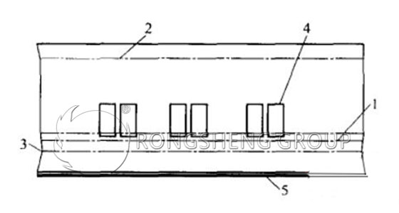
1-Reference point; 2-Horizontal control line; 3-Brick layer diagram; 4-Cathode window; 5-Trough shell bottom plate
Trough bottom insulation construction
The construction of the trench bottom insulation includes the laying of asbestos boards, insulation boards, and insulating bricks, all using dry-laying. When laying boards and bricks, they should be laid from the transverse center of the trench outwards, avoiding continuous joints, and gently tamped down with a wooden mallet. Boards and bricks are cut with a saw, and all gaps in each layer are filled with alumina powder. Gaps between boards/bricks and the trench perimeter are filled with dry-applied waterproofing material or refractory granules and compacted. Damaged insulation boards must be reworked by sawing, and their dimensions must be 2/3 of the design specifications. Local fabrication of insulation boards is also permitted depending on the trench bottom deformation, but the fabricated thickness should not exceed 10mm. Each layer of bricks should be laid with staggered joints, with gaps less than 1mm.
Refractory Brick Construction at the Bottom of the Tank
After laying a layer of alumina powder or refractory granules on the surface of the insulating bricks according to design requirements, use a plumb bob to lay the bricks layer by layer, creating a long plumb bob. Mark the longitudinal brick rows on its upper surface. During construction, use a plumb bob clamp on the brick layer to be laid, and use a plumb bob to hang lines on the plumb bobs on both sides. This controls the thickness and longitudinal arrangement of the bricks, ensuring accurate construction. The plumb bob construction at the bottom of the tank is shown in Figure 2.
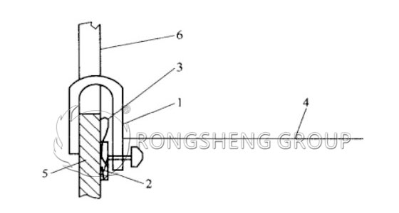
1-Clamp; 2-Plumb bob; 3-Plumb bob; 4-Line; 5-Side plate of the tank shell; 6-Cathode window
The mortar joints of the refractory bricks should be more than 90% full. The top joints, side joints, and horizontal joints should be laid according to design requirements. Fill the gaps around the masonry with refractory granules and compact them. After completion, clean the surface and check against the pre-drawn baseline. Measure nine points on the masonry surface; if any problems are found, address them until the standard is met. Its surface flatness requirement is no greater than ±2mm.
Construction of Dry-Type Impermeable Material at the Bottom of the Trench
Before laying the dry-type impermeable material on the insulating bricks, first, according to the pre-calculated compression ratio, make a special steel template of a certain height, which is used in conjunction with a screed. Generally, the dry-type impermeable material is compacted in two layers. After the first layer is added to the calculated height, it is leveled with a screed, and then a plastic film and a 1mm thick cold-rolled steel plate or plywood are laid on top to prevent dust during compaction. A special reciprocating tamper (approximately 6500 tamps per minute) is used to compact it according to the designed line and number of passes. After the first layer is completed, check whether the compacted height of the impermeable material reaches its compression ratio. After passing the check, lay the second layer, compacting the impermeable material to the designed elevation using the same method. After compaction, measure 9 points on the surface of the impermeable material according to the pre-drawn baseline for inspection. Any areas exceeding the standard can be repaired to achieve a levelness of ±4mm, ensuring the installation dimensions of the cathode carbon blocks.