Hollow microspheres, as dispersible particles, are widely used in refractory material production. In use, they act as aggregates in various heat-resistant materials. Due to their unique properties and structure, nanostructured Al2O3 microspheres are used as raw materials in a variety of products, such as filters, porous lightweight bricks, bubble alumina brick, and refractory products. Hollow Al2O3 microspheres can be used to prepare refractory materials with porous structures and low firing shrinkage. A promising development direction is the preparation of high-porosity ceramic materials through the compaction of nanostructured hollow microspheres.
Hollow Alumina Microspheres
Melted-blown alumina is a common method for preparing hollow alumina microspheres. This method involves melting industrial alumina at high temperature and then using compressed air or oxygen to blow the molten alumina into small spherical shapes, ultimately forming hollow alumina microspheres. The specific steps are as follows:
Industrial alumina containing more than 98% alumina is placed in an electric arc furnace for high-temperature melting. During the melting process, fluxes and stabilizers can be added to increase the melting temperature and stabilize the molten pool.
The molten alumina is then sprayed through nozzles while a pressure valve is opened, using compressed air or oxygen to ablate the liquid alumina into small spherical shapes.
During the blowing process, the flow rate and pressure of the nozzles need to be controlled to ensure that the size and shape of the hollow alumina microspheres are consistent. The blown hollow alumina microspheres need to be screened to remove broken or unsuitable microspheres.
Characteristics of Hollow Alumina Spheres
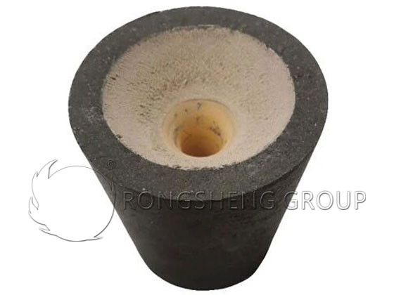
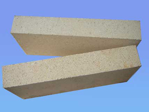
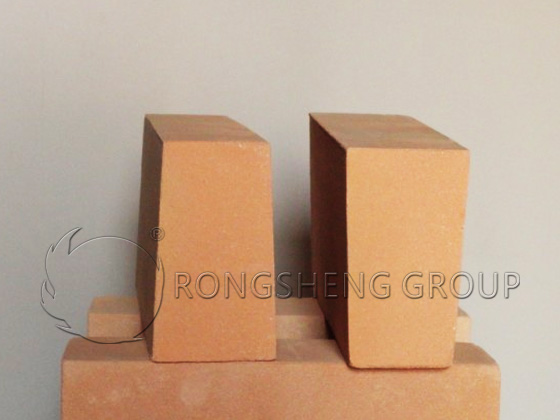
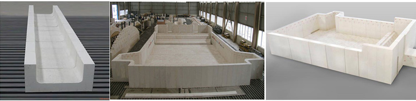
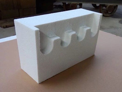
Hollow alumina spheres are lightweight refractory bricks made from industrial alumina using an electro-melting and blowing method. bubble alumina brick, Lightweight refractory insulating bricks made from hollow alumina spheres can be used as linings in high-temperature furnaces in contact with flames.
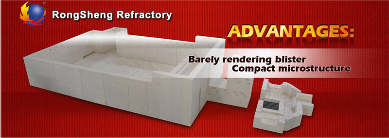
- High operating temperature: Up to 1750 degrees Celsius or higher, with good thermal stability. Low reheat linear shrinkage rate, resulting in longer service life.
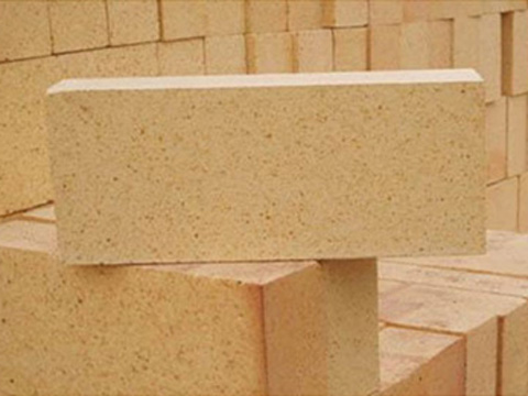
- Optimized structure and reduced furnace weight: Currently used high-temperature resistant materials are heavy bricks with a bulk density of 2.6-3.0 g/cm³. bubble alumina brick, Hollow alumina sphere bricks, however, have a bulk density of only 1.1-1.5 g/cm³. For the same cubic meter volume, using hollow alumina sphere bricks can reduce weight by 1.1-1.9 tons.
- Material savings: To achieve the same operating temperature, the price of heavy bricks is comparable to that of hollow alumina sphere bricks. Furthermore, a considerable amount of refractory insulation material is required. Using alumina hollow sphere bricks can save 1.1-1.9 tons of heavy bricks per cubic meter, and even more, 80% of refractory insulation materials can be saved.
- Energy Saving: Alumina hollow spheres have significant insulation properties and a low thermal conductivity, providing excellent insulation. This reduces heat loss, improves thermal efficiency, and thus saves energy. Energy savings can reach over 30%.
Production Process of Hollow Alumina Spheres
- Alumina raw materials are melted into a liquid state in a tilting electric arc furnace.
- The furnace is then tilted at a certain angle, allowing the molten liquid to flow out of the casting trough at a certain speed. The liquid flow is then dispersed by a high-speed airflow of 0.6-0.8 MPa through a flat nozzle at a 60°~90° angle to the flow stream, thus forming hollow alumina spheres.
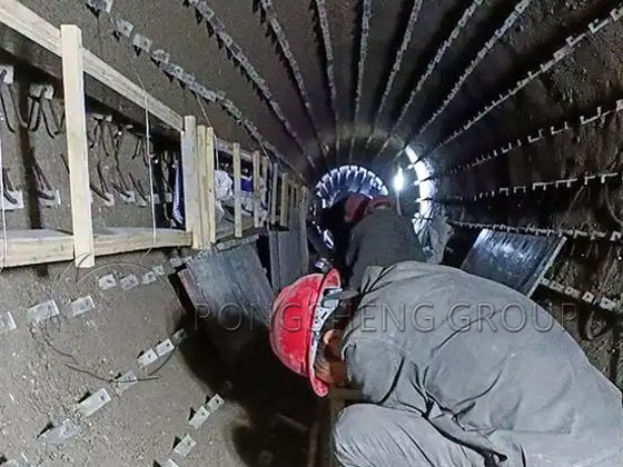
- Hollow alumina spheres have high temperature resistance and good utilization efficiency. Due to their special structure, they can effectively reduce the weight inside the furnace. Hollow alumina spheres have significant heat insulation effects, thereby reducing heat loss and achieving energy saving. Before construction, hollow alumina spheres must be cleaned to achieve better adhesion. Clean water must be used for mixing, and the mixing time must be carefully controlled. The mixed material should be used immediately.
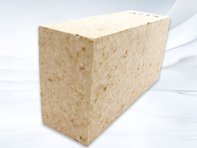
For high-quality bubble alumina bricks, please choose Rongsheng Refractory Materials Manufacturer. Contact Rongsheng for free samples and quotations.